
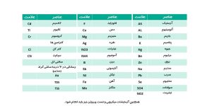
- The water entering the HDF devices must be ULTRA PURE and have a microbial and pyrogenic contamination of less than 0.1CFU/ml and 0.03EU/ml respectively, and an electrical conductivity of less than 2µS/cm, which the two-stage RO system must be able to provide, and in terms of other chemical/physical parameters, it must comply with ISO 13959 or ISO 23500 or AAMI standards. The list of desired parameters is listed in the table below.
List of required water tests for dialysis units
- The required water volume for each HDF machine should be considered 60 liters per hour. Also, the water storage tank for the pre-treatment system and the RO machine should be considered for emergencies (water cut-off). The volume of this tank should be at least twice the total consumption of the dialysis machines in one work shift (about 5 hours). Also, the tank should be capable of periodic cleaning.
- The entire loop of RO water (back and forth) of the dialysis section should have a minimum of connections and be made of stainless steel with angles of at least 135 degrees. The valve and all connections of the purified water (RO) outlet to the dialysis machine should be made of stainless steel with an internal diameter of 3.8 inches. This valve should be of the gas valve type and be placed vertically (downward). It is better to consider a horizontal distance of 15 centimeters from the right side to the dialysis machine for the installation location of this valve. A stainless steel dialysis water sampling valve should be provided in this path.
- The RO water pressure for entering the hemodialysis machine should be in the range of 2bar to 4bar. The temperature of this water entering the hemodialysis machine should be between 15 and 25 degrees Celsius.
The inlet and outlet hoses that must be provided by that respected center for HDF machines must be opaque, medical type, with two different colors, and withstand a pressure of at least 10 bars in order to prevent the growth of bacteria. The inner diameter of each inlet and outlet hose must be 3.8 inches and the length of each must be 2.5 meters. - The height of the purified water inlet pipe (RO) to the hemodialysis machine should be at a height of 50 to 70 centimeters from the ground.
- The outlet height of the dialysis sewage duct should be in the range of 20-40 centimeters from the ground and should also be located lower than the outlet of the dialysis filter. The dialysis sewage duct should have a diameter of 2 inches. The entrance to this duct should be covered with a plastic cap with a hole the size of the diameter of the dialysis outlet hose, which is placed in the middle of the cap, so that the outlet hose enters vertically and does not come into contact with the body of the sewer. There should be at least 10cm of air space between the end of the dialysis machine’s wastewater outlet hose and the dialysis wastewater path.
- The floor of the dialysis section and the RO room should be acid-resistant and disinfectable. The walls of the dialysis section should also be disinfectable. There should be a slight slope on the surface of the dialysis section towards the sewage of the floor washers. The surface of the dialysis section should not be slippery. The floor washers of the dialysis section should have covers.
Wastewater from dialysis machines, wastewater from dialysis ward floor washers, and wastewater from dialysis ward washrooms must be separate from each other.
- The space required for each dialysis machine and dialysis bed (or chair) should be at least 2.70 x 2.70 square meters and, when necessary, separated from the adjacent bed and machine with a curtain or screen. A pedestal-free washbasin should be installed between every dialysis bed/chair. The width of the dialysis ward corridor should be at least 1.25 meters.
- The location of the hemodialysis machines should be suitable in terms of humidity, temperature, and ventilation. The air temperature should be in the range of 22 to 24 degrees Celsius and the relative humidity of the air should be in the range of 30% to 60%. It is necessary to install a temperature and humidity meter in the dialysis ward to control the aforementioned parameters.
- The air in the dialysis ward should be replaced at least 6 times per hour, with fresh air being replaced at least 4 times.
The pressure in the dialysis ward should be positive. The pressure in the isolation room should be negative.
- For each dialysis machine and bed, there should be 4 16-amp electrical outlets with a protective earth connection (pin), each installed at a height of 120 to 150 centimeters from the ground. If a dialysis chair is used, this height should be 140 to 160 centimeters from the ground. In addition, for essential cases, two emergency electrical outlets should be installed for each dialysis machine and bed. A 16-amp automatic fuse should be considered for each of the installed outlets.
- The input voltage for the dialysis machine should be 230 volts alternating current with a frequency of 50 Hz.
- A UPS (zero second) device should be used to prevent damage to electrical and electronic components from power fluctuations and power supply to dialysis machines during power outages. Otherwise, for centers that do not have power outages and do not have the possibility of providing a UPS, they should at least use a stabilizer with an automatic bypass system with the necessary electrical power. However, if one of the aforementioned devices is not installed, even during the warranty period, all possible damage resulting from the failure to use an appropriate power supply system is the responsibility of that center. If an emergency power generator is used during a power outage, a stabilizer with an appropriate capacity should also be used to prevent damage to the patient and dialysis machine components.
It should be explained that the electrical power required for the UPS device or stabilizer required for each dialysis machine should be at least 2500 watts or 7.2 KVA considered.
- A suitable protective earthing system must be available or provided. There must be no voltage on the protective earthing system at any time. The total resistance from the protective earthing pin of the dialysis unit sockets to the electrical well must be less than 2 ohms. The protective earthing must be capable of carrying currents in excess of 100 amps. A copy of the latest test report must also be sent to this company.
- The location of all equipment must be level.